Drawing and scan to BIM
AI Scan-to-BIM & Digital Twins
- Scans, PDFs and point clouds
- Walls, rooms and openings classified
- DXF and JSON output
1/4Start from a laser scan, a point cloud slice or a scanned legacy drawing. Noise and clutter are expected.
The manual drafting drag
Existing buildings rarely come with a usable model
Architecture, property development and facility teams lose days tracing old blueprints and laser scans by hand before any real work starts. That slows renovation proposals, delays due diligence and leaves building operations running on paper.
Days of tracing
Every wall, door and room is redrawn by hand from a scan or an old sheet before design can begin.Legacy drawings
Paper blueprints are skewed, faded and full of tiny rotated labels that ordinary OCR can't read.Noisy scans
Point clouds capture everything, including furniture and clutter. Someone still has to decide what is a wall.One miss breaks the model
Skip a single door and room connectivity is wrong, which breaks areas, egress and adjacency downstream.
| Topic | Manual redrawing | AI scan-to-BIM pipeline |
|---|---|---|
| Speed | Days of tracing per building level | Walls, openings and rooms extracted automatically per sheet or scan |
| Structure | Lines on a layer, with meaning kept in someone's head | Classed elements: walls, spaces, doors and windows with attributes |
| Labels | Room names and dimensions retyped by hand | Rotated text read and mapped to the right room |
| Traceability | No record of where each element came from | Each element links back to its source location |
How it works
From pixels and points to building elements
Each stage does one job with the precision it needs. Geometry is measured by trained models first; rules and reasoning work on that structured result, not on guesses.
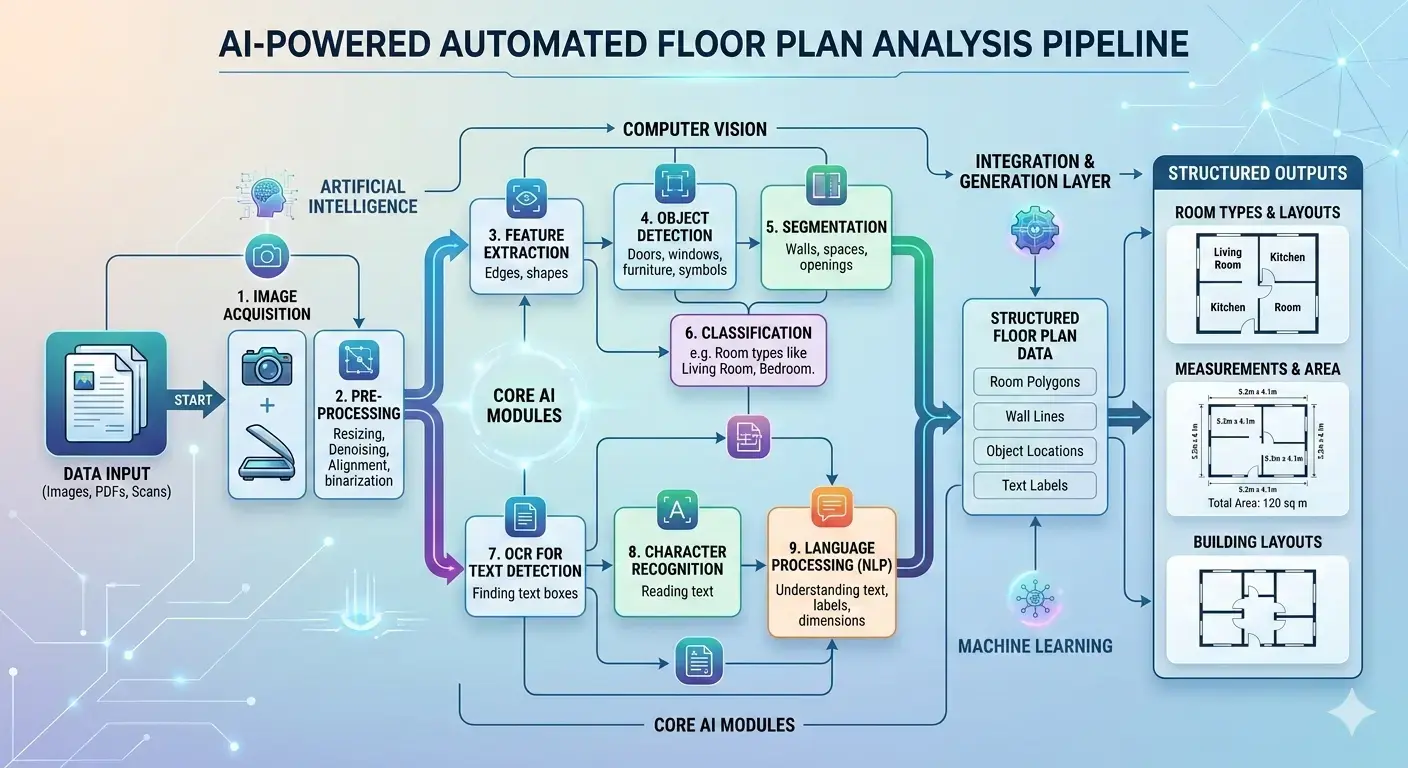
- Stage 1
Ingest and prepare the source
Scanned sheets and PDFs are deskewed, denoised and tiled into overlapping 1024 px patches so fine line work survives. The scale is read from the drawing. Point cloud scans are prepared so structural geometry can be classified directly from the scan set.Clean, calibrated input - Stage 2
Segment walls into vector centerlines
A segmentation network classifies wall pixels, separating interior from exterior walls, and the mask is converted into clean centerline vectors with thickness.Wall centerlinesHRNet-W48U-Net - Stage 3
Detect doors, windows and fixtures
Detectors with oriented bounding boxes find openings in the walls, including door swing direction, plus stairs and fixtures.Openings with size and swingYOLO (OBB) - Stage 4
Read rotated labels and dimensions
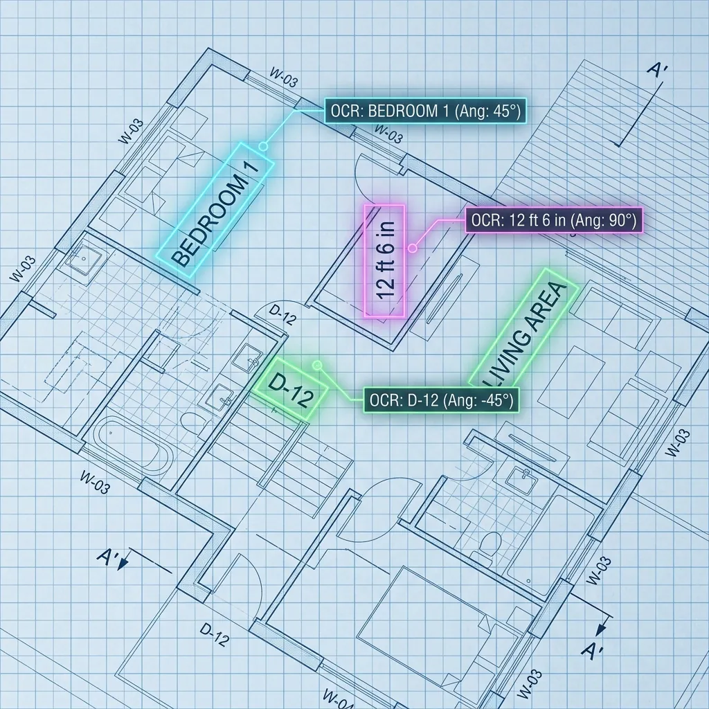
OCR tuned to engineering fonts reads room names, dimension strings and tags at any angle, and maps each value to the nearest room centroid or element.Names, heights, widthsDBNetCRNN - Stage 5
Build space topology
Openings are closed to form room polygons, and a graph records which rooms and corridors connect through which doors.Rooms and adjacency graph - Stage 6
Validate and export
Elements carry their class, attributes and source location. Low-confidence items are flagged for review, then geometry and metadata are exported for your tools.BIM-ready elementsDXFJSONCSV
What you get
Structured building data, not a picture of a plan
We scope the element classes and attributes to the model or database you are filling.
Vector wall geometry
Pixel boundaries mapped to clean vector centerlines, with interior and exterior walls classified.DXF centerlinesCompare models for plansRooms and spaces
Closed room polygons with names and areas, plus the adjacency graph that says how spaces connect.Polygons, areas, adjacencyHow floor plan analysis worksDoors and windows
Every opening located in its host wall, with width and swing direction attached as attributes.Openings with attributesSymbol extraction explainedLabels and metadata
Room names, heights and door widths read from tiny, rotated text and written into your data files.Metadata in JSONReading rotated blueprint textPoint cloud fitting
Structural geometry classified directly from 3D scan sets, separating walls and floors from furniture and clutter.Semantic geometry from scansCompliance-ready models
The same building model supports checks such as door widths and egress before plans go to review.Issues flagged per room and doorBuilding code compliance
In practice
Where teams use scan-to-BIM automation
Renovation proposals from old blueprints
- Scanned paper and PDF drawings
- Room names and dimensions mapped to spaces
- Quantities available for estimating
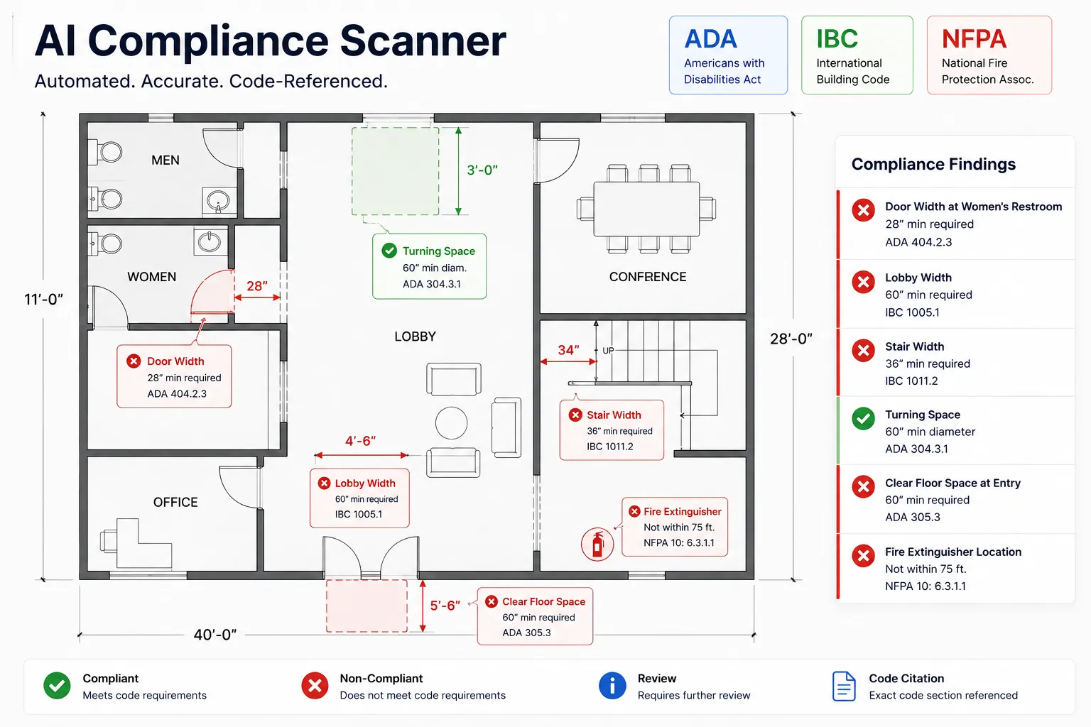
Due diligence and compliance audits
- Door and corridor widths measured
- Findings reference the plan location
- Engineers review before anything is approved
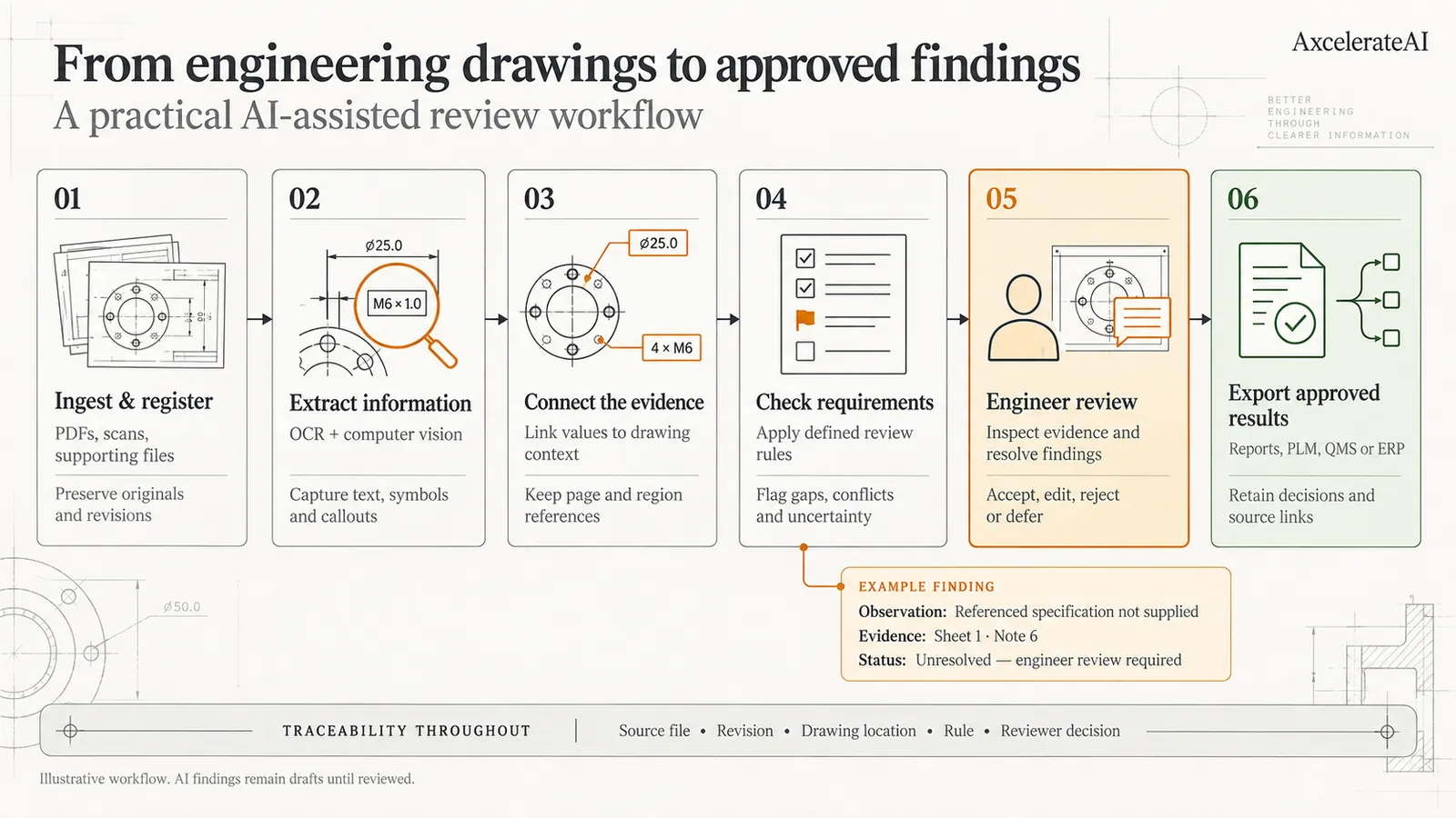
Engineering drawing review with evidence
- Originals and revisions preserved
- Unresolved values stay unresolved
- Reviewer decisions exported with source links
Digital twins for building operations
- Rooms and assets with stable IDs
- Metadata loaded into your facility database
- Updated when a new scan or drawing arrives

Why a custom pipeline
A building model can't be approximately right
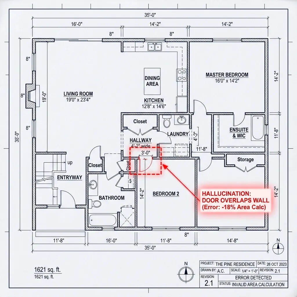
Visual LLMs are useful on photos but unreliable on drawings. They struggle with long sheet aspect ratios and dense line work, and they invent or drop walls and doors.
- Walls come from segmentation, not description
- Doors come from detectors trained on drawing conventions
- Room connectivity is computed, so a missing door is caught
- Every element keeps a link to its source
Fits your workflow
Delivered into the tools you already use
The output is built around the model, template or database you need to fill, not the other way round.
Confidential drawings can stay on your network with a private deployment. Read how we handle data on our security page, or see our custom computer vision services.
DXF geometry
Walls, openings and room boundaries as vector geometry for CAD and BIM tools.JSON metadata
Room names, areas, heights, door widths and adjacency in a schema you agree with us.API or batch
Call it from your platform, or drop in a whole archive of drawings and scans.Private deployment
Run it in your cloud or on your own servers when building data is sensitive.
Getting started
Prove it on your own drawings and scans
Start with a few representative buildings and models your team has already produced by hand as the benchmark.
Step 1: Scoping call
30 minutes
We look at sample drawings or scans, the elements you need and the format your tools expect.
- NDA on request
Step 2: Proof of concept
4–6 weeks
A working pipeline on your files, measured against your existing hand-built models.
- Accuracy targets agreed up front
Step 3: Production
Ongoing
Integrated with your CAD, BIM or facility systems, monitored and retrained on new drawing conventions.
- You own the IP
Not sure where AI fits yet? Start with an AI Opportunity Audit.
FAQ
Questions, answered
What architecture, construction and facility teams ask before a pilot.
Working on construction drawings? See AI for construction.
Legacy 2D floor plans and blueprints (scanned paper, raster images or PDFs), CAD exports, and point cloud laser scans. Drawings are deskewed, cleaned and tiled before analysis; structural geometry is classified directly from the scan set.
Vector wall centerlines, closed room polygons, doors and windows with their widths, and room names and labels read from the drawing. Geometry is delivered as DXF, and the metadata as JSON (or CSV) so it can be loaded into CAD and BIM tools such as Autodesk Revit, or into your facility database. We confirm the exact target format for your tools during scoping.
A pipeline of specialists rather than one model: HRNet-style segmentation for wall pixels, YOLO detectors with oriented bounding boxes for doors and their swing direction, and rotated-text OCR (DBNet and CRNN) for labels and dimensions. Rules then close openings into room polygons and build the adjacency graph.
General vision-language models struggle with the aspect ratios and dense line work of drawings. They miss or invent walls and doors, and a single missed opening breaks room connectivity. Measuring geometry with trained models first keeps the output traceable.
Every element keeps a link to where it was found on the source sheet or scan, and low-confidence items are flagged for review rather than filled in. In a pilot, we measure the output against drawings your team has already modelled by hand.
Yes. Drawings and scans of existing buildings are often confidential, so the pipeline can run in your cloud or on your own servers. A proof of concept on your files typically takes 4–6 weeks.
Related
Keep exploring
- Construction & drawingsFloor plan analysisRooms, walls, doors and symbols read from drawings and returned as structured data.
- Construction & drawingsAI quantity takeoffCounts, lengths and areas measured from construction drawings into an estimator-ready takeoff.
- IndustriesConstruction and AECDrawing intelligence for estimators, builders and compliance teams.
- Computer visionCustom computer vision modelsModels trained on your own images, video and edge cases.
Book a strategy session
Talk to an AI engineer about your project
Tell us what you want to automate. The first call is a 30-minute working session with an engineer, not a sales pitch.
- Send the form, it takes 2 minutes
- We reply within 1 business day, under NDA if you need it
- A 30-minute call to scope feasibility and next steps