TL;DR: A residential takeoff — extracting ~31 parameters like floor area, room counts, door/window totals, bench lengths, and roof dimensions from architectural plans — typically takes hours of careful manual work. AxcelerateAI's hybrid floor plan analysis pipeline combines vector geometry parsing (DXF/PDF), computer vision symbol detection, intelligent OCR, and LLM-based spatial reasoning to deliver a filled, audit-traceable Take-Off Parameters (TOP) spreadsheet in seconds, with >98% accuracy.
Residential construction estimating often starts with a takeoff: manually extracting dozens of parameters from floor plans, roof plans, and door/window schedules. For a typical single-family home project, an estimator might track a fixed list of roughly 31 parameters — floor and roof areas, wall perimeters, room/door/window counts, kitchen bench lengths, vanity lengths, and more.
Doing this by hand is slow and inconsistently reproducible. A missed room, a mis-read dimension, or an overlooked door schedule entry can cascade into under-bids, material shortfalls, or compliance gaps. Industry analysis confirms that modern AI pipelines can reduce this effort to seconds with >98% accuracy.
At AxcelerateAI, we turn drawings — floor plans, schedules, and roof plans — into structured data so estimators get precise results and traceable answers. This post explains exactly how, using three real use cases from residential construction projects.
Related Reading: Before diving in, see our AI Floor Plan Spatial Analysis guide for the foundational pipeline, and Why LLMs Fail on Floor Plans to understand why off-the-shelf vision models alone can't solve this.
The Four-Stage AI Pipeline for Residential Takeoffs
Our pipeline is not a single AI model. It is an assembly of specialist tools, each solving one sub-problem with the precision that sub-problem demands. Think of it as four complementary layers stacked to handle what none could do alone.
Stage 1 — Vector Data Extraction (DXF/PDF)
The first stage is deterministic, not AI. We parse the CAD data directly.
Using tools like ezdxf and Shapely, we read vector lines, walls, and dimension entities to get exact lengths and areas from DXF exports. DXF is always preferred when available — it yields true coordinates from the drafting application with no loss of precision. PDF parsing is used only when a DXF is unavailable; in that case, we fall back to reading printed dimension text, which introduces more uncertainty.
From DXF geometry, we extract:
- Wall lengths and perimeters (exact to millимetre resolution)
- Floor polygon areas (computed from wall boundary vectors)
- Roof geometry (where a roof plan DXF is provided)
- Dimension strings annotated in the drawing
The output is a raw geometry model of the building — walls as line segments, rooms as polygons, roofs as plane faces — ready for the next layer.
Stage 2 — Object & Symbol Detection
In parallel with vector extraction, we run computer vision across the drawings.
Custom-trained neural networks — semantic segmentation for room boundaries and YOLO-based object detectors for specific symbols — scan every page of the plan set to identify:
- Doors: single-swing, double-swing, sliding, bi-fold
- Windows (all types)
- Stairs, columns, fixtures
- Kitchen bench and vanity elements (detected by shape/symbol convention)
Critically, these models are trained specifically on architectural line-art conventions, not photographs. As explained in our Best AI Model for Floor Plan Analysis deep dive, general-purpose detectors fail completely on plan-view CAD symbols. Our models are tuned to the regional drafting conventions of your drawing set.
The result: every element on the plan is located, classified, and linked to a bounding box for the next stage to reference.
Stage 3 — OCR & Text Extraction
Blueprints contain enormous amounts of text: room names, dimension annotations, title blocks, door tags, and schedule tables. The challenge is that this text is rotated, overlapping, and printed in architectural typefaces that standard OCR engines misread.
We use an Intelligent OCR (I-OCR) pipeline — DBNet for angle-aware text region detection, CRNN for transcription tuned to engineering fonts — to extract:
- Room names and labels (to associate with detected room polygons)
- Door tags (e.g., "D102", "FD-22A") for cross-referencing schedules
- Dimension strings (to validate or supplement vector geometry)
- Door and window schedule tables (fire ratings, leaf widths, hardware sets)
For an in-depth look at this problem, see our post on Solving Blueprint OCR & Rotated Text, which covers the full range of blueprint-specific text challenges.
Stage 4 — Spatial Reasoning & LLM
After the first three stages, we have: a geometry model, a set of detected elements with locations, and extracted text. The final layer assembles these into a coherent knowledge graph of the building, and an LLM (or rule engine) then "reads" the structured data to answer estimator queries.
This is where context is applied:
- Doors are associated with the rooms they connect
- Door tags are cross-referenced to the schedule to retrieve fire ratings, widths, and materials
- Room polygons are labeled with their OCR-extracted room names
- Spatial relationships — "which room does this door open to?" — are resolved by graph traversal, not pixel guessing
This two-layer design (exact geometry + intelligent reasoning) is the key differentiator from pure LLM image analysis. The LLM operates on structured data, not fuzzy image pixels — so it doesn't hallucinate wall counts or guess room dimensions. It reasons over facts.
As we discuss in Why LLMs Fail on Floor Plans, raw vision-language models like GPT-4V simply cannot perform the spatial math or topological reasoning that this stage requires.
Stage 5 — Output & Validation
The pipeline generates a filled Take-Off Parameters (TOP) spreadsheet matching the builder's standard template.
What distinguishes our output:
- Every value is sourced: each cell links back to the PDF page, DXF layer, or schedule table it came from
- Flagging, not guessing: if a roof plan is missing, the hip/valley lengths field is flagged as "Not Calculated — Roof Plan Required" rather than guessed
- Confidence scores: low-confidence values (e.g., a room whose OCR name was partially obscured) are surfaced for human verification rather than silently accepted
Use Case 1: Fire-Rated Door Detection & Compliance
Challenge: Identify which doors serve an egress corridor and confirm their fire rating. Manual plans have door schedules, but linking tag numbers to spatial locations is tedious — and an error is a code violation liability.
AI Solution:
The system detects all door symbols on the plan and reads their schedule tags via I-OCR. It cross-references the door schedule to extract each door's fire rating (e.g., "90 min"). It then maps spatial relationships — using the room adjacency graph — to determine which rooms each door connects. Doors on egress paths to stairwells or exterior exits are flagged as egress-critical.
Finally, the rule engine applies the relevant code checks (NFPA 80, IBC § 716) and generates a compliance status per door.
Output example:
Door D102 — 90 min — Office 2 → Corridor — ✓ Compliant
Door D108 — 60 min — Server Room → Corridor — ⚠ Check: IBC § 716.5.3 requires ≥ 90 min at stair
Door D115 — No rating in schedule — Storage → Corridor — ✗ Schedule entry missing
Because the result is fully structured, an estimator can verify in minutes rather than days — and a compliance gap found in pre-submission review is worth far more than one found during plan check.
For the full technical breakdown of this pipeline, see our dedicated post on Fire-Rated Door Detection & Compliance.
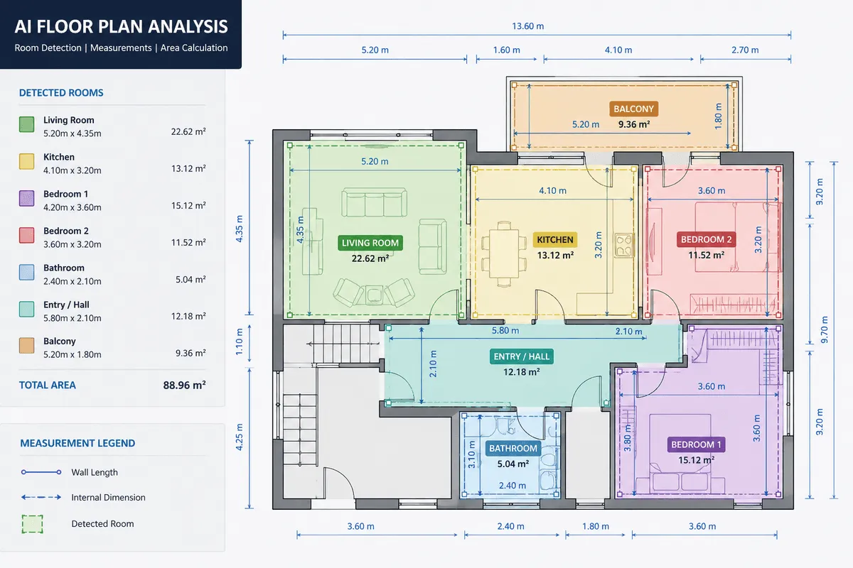
Use Case 2: Room & Area Analysis
Challenge: Calculate the area and dimensions of every room, group them by type, and produce total floor area, room-by-room breakdowns, and interior/exterior area splits.
AI Solution:
The AI segments the floor plan into room polygons using the detected wall lines and break points. Once walls are segmented and doors are located, each enclosed space is reconstructed as a polygon. Room names extracted via OCR are matched to each polygon. Areas are calculated from the exact CAD coordinates — not estimated from pixels.
For each room, the system also tallies associated doors and windows.
Output example:
| Room | Area | Doors | Windows |
|---|---|---|---|
| Master Bedroom (101) | 285 ft² | 2 | 3 |
| Bedroom 2 (102) | 210 ft² | 1 | 2 |
| Living Room (103) | 348 ft² | 1 | 4 |
| Kitchen (104) | 192 ft² | 1 | 2 |
| Dining Area (105) | 164 ft² | 0 | 2 |
| Garage (106) | 412 ft² | 2 | 1 |
From that structured output, higher-level queries become trivial: "What is the total carpetable area on Level 1?", "List all rooms larger than 200 ft²", "How many windows are in the bedroom wing?"
This is invaluable for space planning, permitting, and material takeoff (flooring, painting, acoustic ceilings).
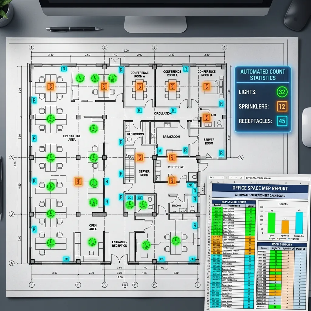
Use Case 3: Building Element & Symbol Extraction
Challenge: Extract counts and lengths of all building elements across the plan set — windows, doors, cabinets, benches, vanities, electrical fixtures, plumbing, smoke detectors — from a combination of visual symbols and schedule tables.
AI Solution:
Object detection models scan every plan sheet for every symbol type. For each detected element:
- Type is classified (hinged door vs. sliding door, single-pane vs. double-pane window, etc.)
- Location is recorded (floor, sheet reference, X/Y coordinates)
- Schedule entry is matched (where a schedule exists)
For linear features — kitchen benches, vanity counters, wall-mounted cabinetry runs — the DXF geometry is used to measure exact lengths. These can't be reliably estimated by counting symbols; they require true vector measurement.
Output example:
Doors:          31 total  (22 hinged, 7 sliding, 2 bi-fold)
Windows:        18 total  (12 single, 6 double)
Kitchen bench:  8.4 m
Vanity counters: 3.6 m
Smoke detectors: 7
Downlights:     24
Each quantity includes drawing coordinates for audit. An estimator can click on "Kitchen bench: 8.4 m" and be taken directly to the source line in the DXF or the annotated PDF highlight.
For a deeper look at symbol extraction methodology, see How AI Extracts Symbols from Floor Plans.
Why Two Layers? (Geometry + AI Reasoning)
The hybrid design is deliberate:
| Layer | Role | What It Solves |
|---|---|---|
| DXF/Vector Parsing | Exact geometry | Wall lengths, floor areas, roof dimensions — no approximation |
| Computer Vision | Symbol detection | Doors, windows, fixtures — identified at their location on the plan |
| I-OCR | Text extraction | Room names, door tags, schedule tables, dimension strings |
| LLM / Rule Engine | Spatial reasoning | Door-to-room associations, schedule cross-referencing, compliance checks |
Asking a single vision LLM to do all of this from a raw blueprint image is like asking someone to calculate a room's area by staring at a photo of a ruler. The information is theoretically visible, but the precision required is simply not achievable that way.
Our builders specifically requested that the system flag when a roof plan is missing rather than estimate hip/valley lengths. That safety behaviour — uncertainty surfaced, not hidden — is only possible in a system where each data source is explicit and traceable.
Proven Benefits & Validation
Industry research confirms that re-engineering the takeoff workflow with AI delivers measurable gains:
- >98% accuracy for structured parameter extraction from well-formatted drawings
- Hours to seconds for a standard 31-parameter residential takeoff
- Full auditability — every value traceable to its source drawing and layer
- Reduced rework — uncertain values flagged before submission, not discovered during construction
Our pipeline is tuned to your drawing conventions: layer names, symbol styles, title block formats, and schedule layouts. This means the system doesn't need to "figure out" your drawings from scratch on each project — it's configured for how your studio or certifier produces plans.
Related Capabilities & Further Reading
Explore connected resources in the AxcelerateAI floor plan intelligence series:
- AI-Powered Floor Plan Analysis: Full Technical Guide — End-to-end pipeline from raw PDF to structured spatial data.
- Best AI Model for Floor Plan Analysis — U-Net, YOLOv11, Mask R-CNN, and GNNs benchmarked.
- Fire-Rated Door Detection & Compliance — Automated fire-door auditing against NFPA 80/IBC codes.
- Why LLMs Fail on Floor Plans — Why GPT-4V and Gemini can't replace custom CV pipelines.
Case Studies:
- AI Offer Memorandum Parsing — How AI extracts structured investment data from 40–150 page real estate documents, similar structured extraction applied to construction documents.
- AI Virtual Staging — How AI transforms unstructured property images into photorealistic, structured visual assets — complementary to how we transform unstructured drawings into structured takeoff data.
Explore our solutions: AI Floor Plan Spatial Analysis | AI Quantity Takeoff & Estimating | Computer Vision for Real Estate